Farbfilter Kit – Build Guide
Some tools you will need#
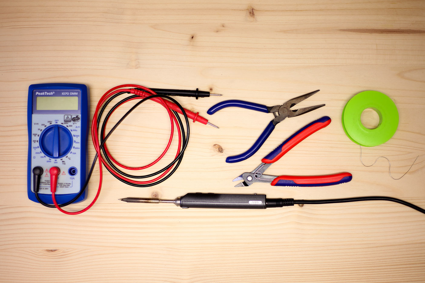
- A spool of solder. We use lead free 0.5mm.
- A soldering iron for electronics A good temperature for soldering lead free solder is 375 - 380° C.
- Snipe-nose pliers
- A Multimeter
Here’s what you will find in the kit#
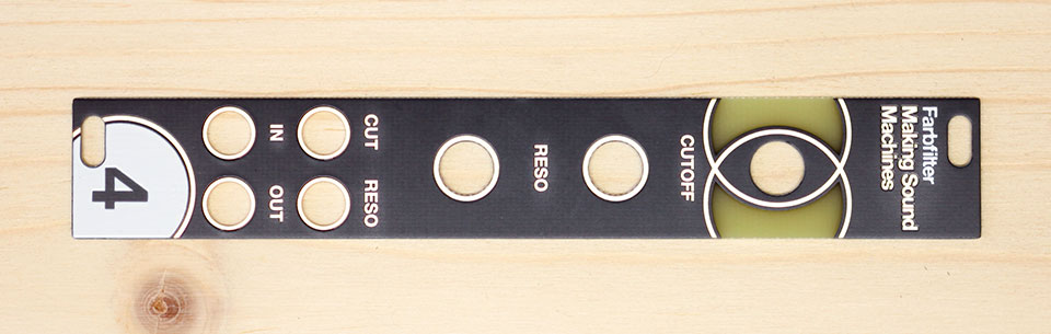

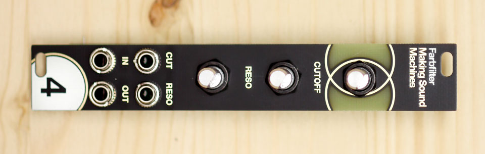
- The frontpanel
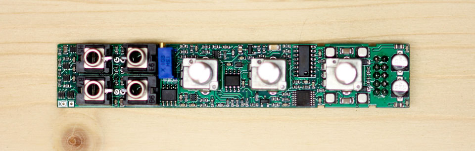
- The PCB with presoldered components
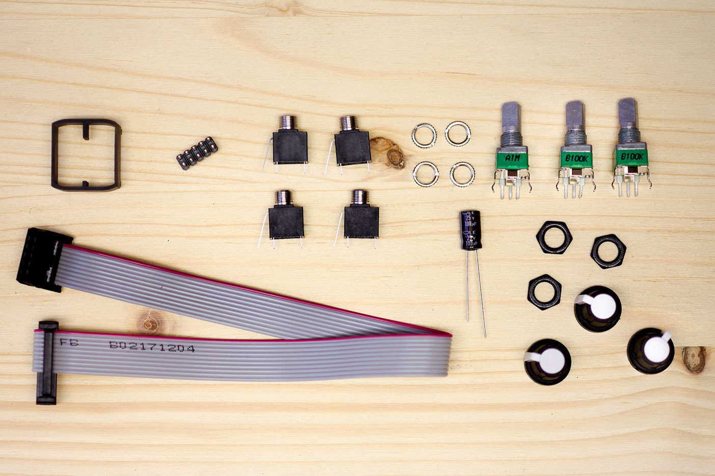
- 4x Thonkiconn jacks, and knurled nuts
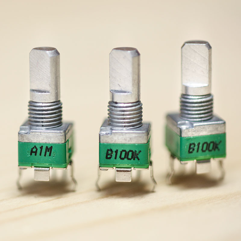
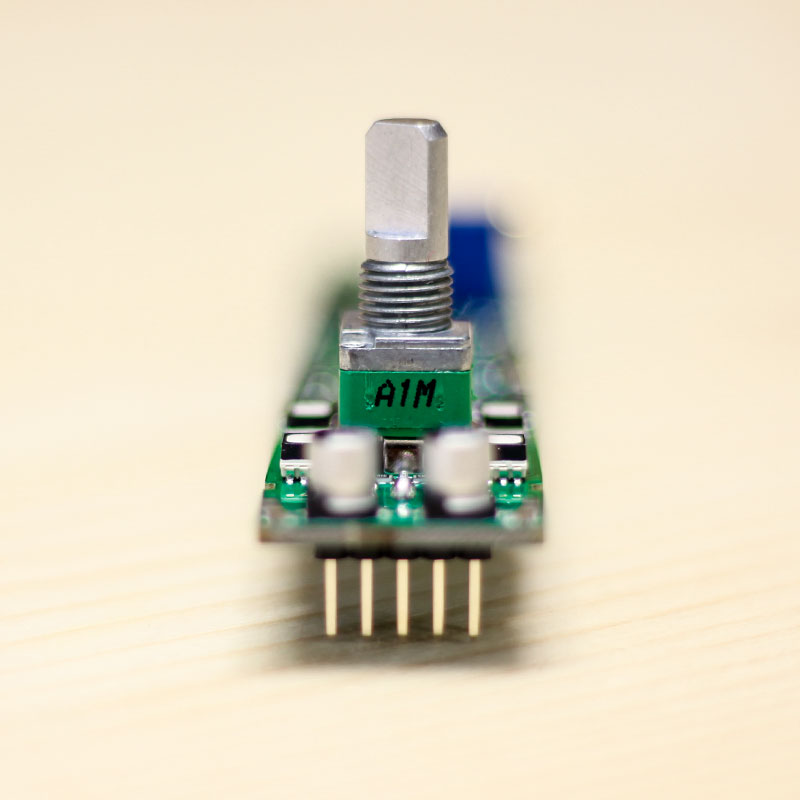
- 1x potentiometer A1M
- 2x potentiometers B100k
- 3x black hex nuts for potentiometers
- 3x Rogan soft touch potentiometer caps
- 1x 2x5 pin header for power
- 1x 100uF/25V through-hole capacitor
- 1x 3D printed light guide for LEDs
- 1x Eurorack power cable
Build Guide#
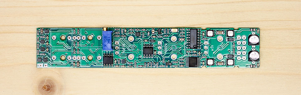
All of the SMD components on the PCB have already been assembled for you, so this is a very quick build. However, it does require very careful and precise soldering.
Avoid touching the SMD components with your hands and be very careful not to touch them with your soldering iron. Take your time, and use an iron with a reasonably small tip.
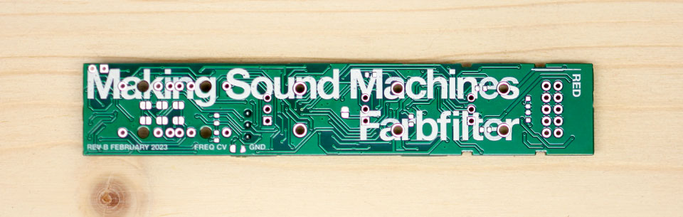
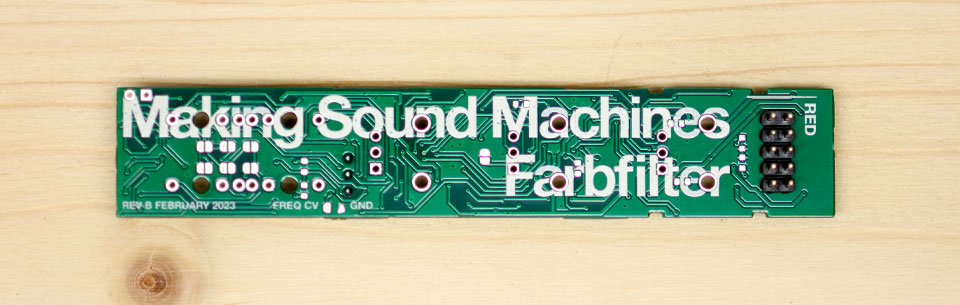
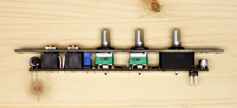
Back side - this side has the module name printed on it.
Turn the PCB over, so that the surface-mount components are facing down - this will be the back side of the module. This side has the module name printed on it.
2x5 Power Header#
Start by placing the 2x5 power header. Make sure that it sits on the correct side: the long pins should be on the same side as the large module name print. The short pins stick through the PCB and should be soldered on the SMD component side.
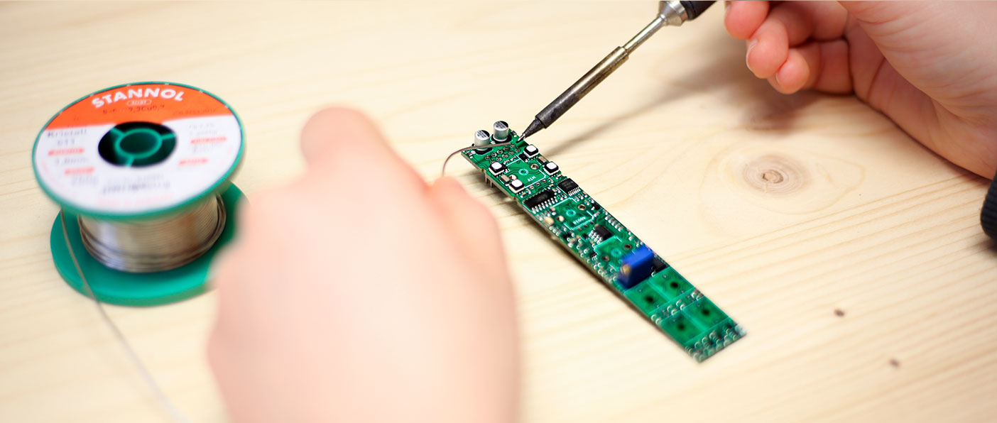
With the SMD component side facing up, solder one bottom row corner pin first. Using a fine soldering tip, you should have enough space to solder the bottom row and avoid touching the SMD electrolytic capacitors at the top.
Check that the pin header sits flush and reheat to adjust if necessary. If the pin header sits flush, finish the bottom row.
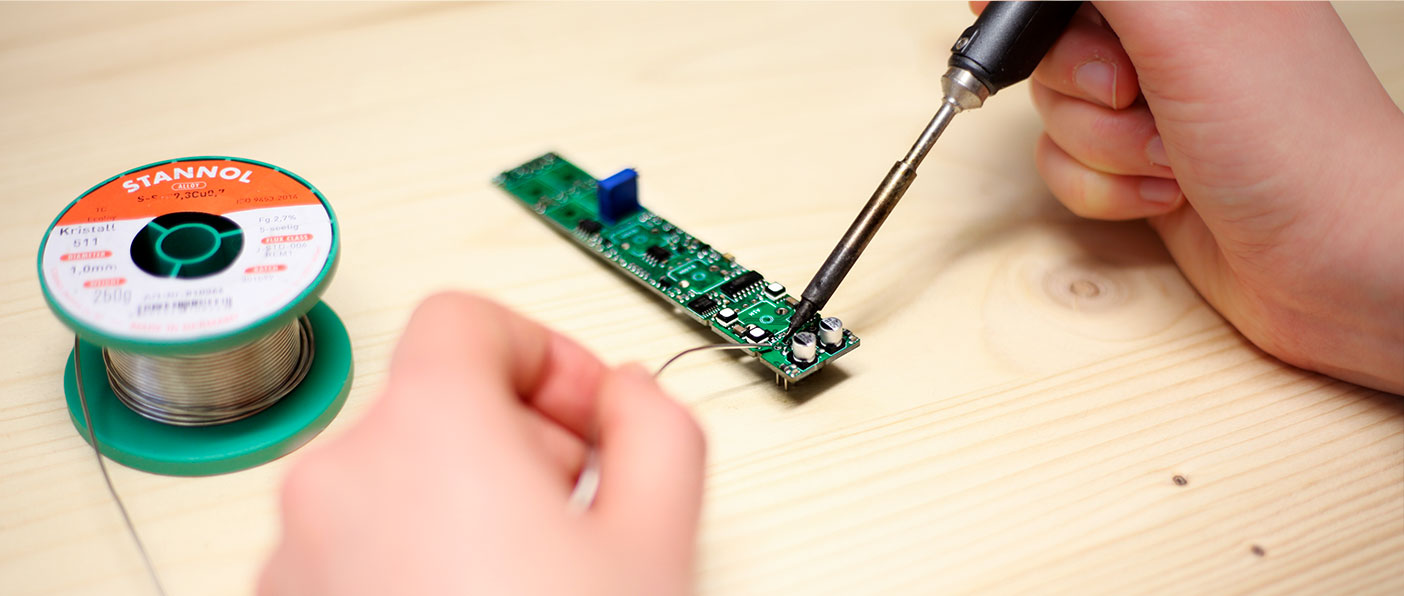
Rotate the PCB so that the SMD electrolytic caps sit at the bottom. It is now easier to access the remaining row of the pin header for soldering.
Finish the remaining row. Again, you should have enough space to solder the remaining row and avoid touching the LEDs.
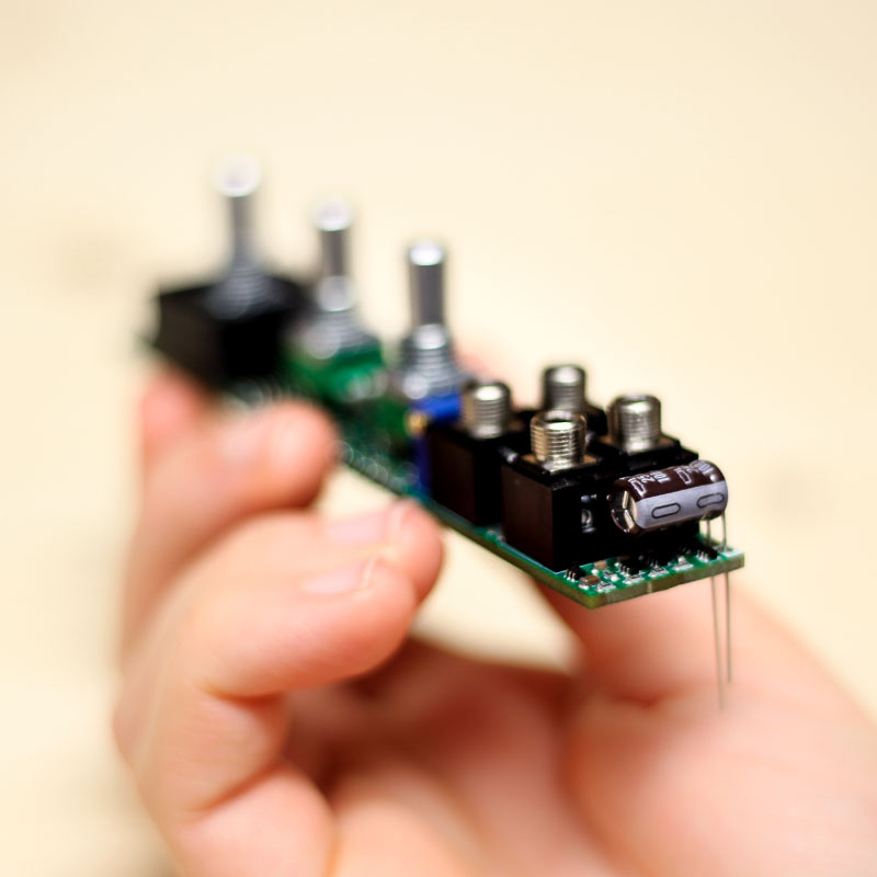
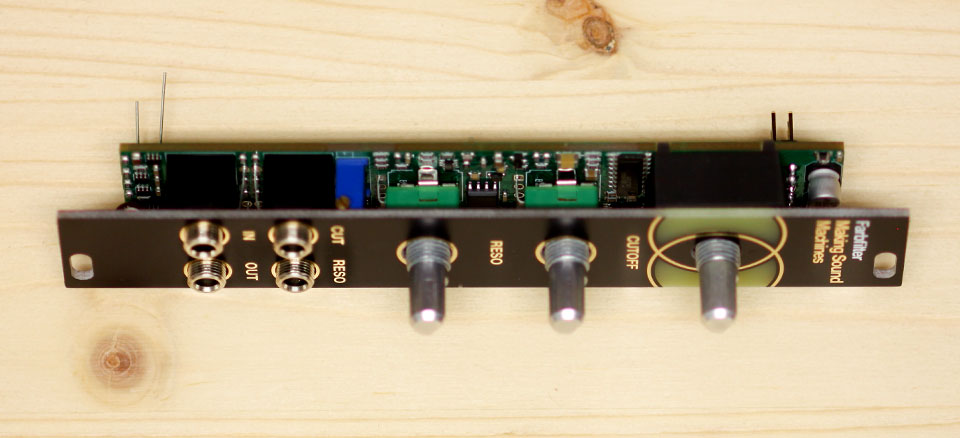
Potentiometers and Jacks#
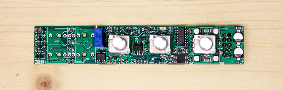
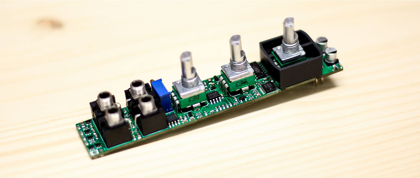
Next, orient the PCB so you can see the side with the SMD components. Place all the components onto the board, but do not solder anything yet.
Place Potentiometers#
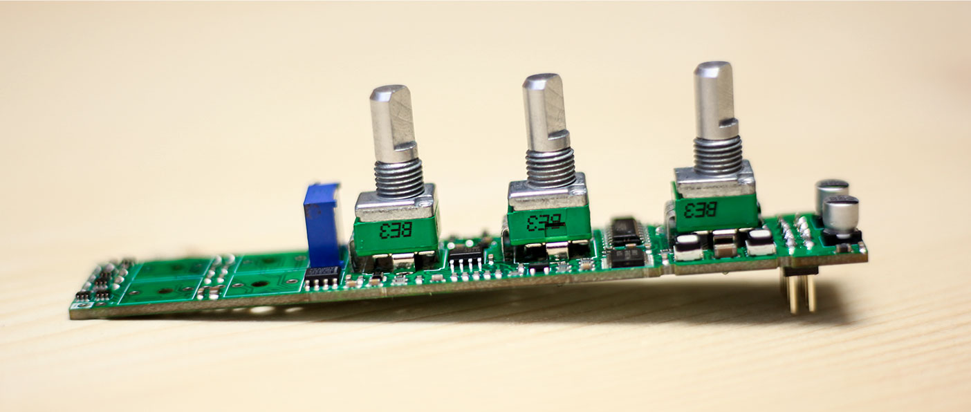
Place the three potentiometers first, as they are the trickiest to place. Check that the value printed on the potentiometer matches the value printed on the PCB.
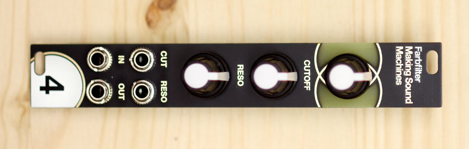
On Farbfilter:
- the top potentiometer is A1M
- the middle and bottom potentiometers are B100k
You may need to squidge the side brackets a little to make them fit. Be gentle as the pins may bend easily if you don’t line them up with the holes. Inspect to make sure all legs stick through the PCB.
Place but do not solder yet.
Warning
Double check that you have placed the right potentiometer values in the correct slots. Once the potentiometers are soldered in, it will be hard to correct a wrong value.
Place Thonkiconn#
The groups of rectangular outlines marked with J and a number indicate where to place the four black Thonkiconn jacks.
Place the jacks but do not solder yet.
Place LED light guide#
Carefully place the 3D printed light guide for LEDs. It goes over the top potentiometer, and you have to make sure it is in the correct orientation.
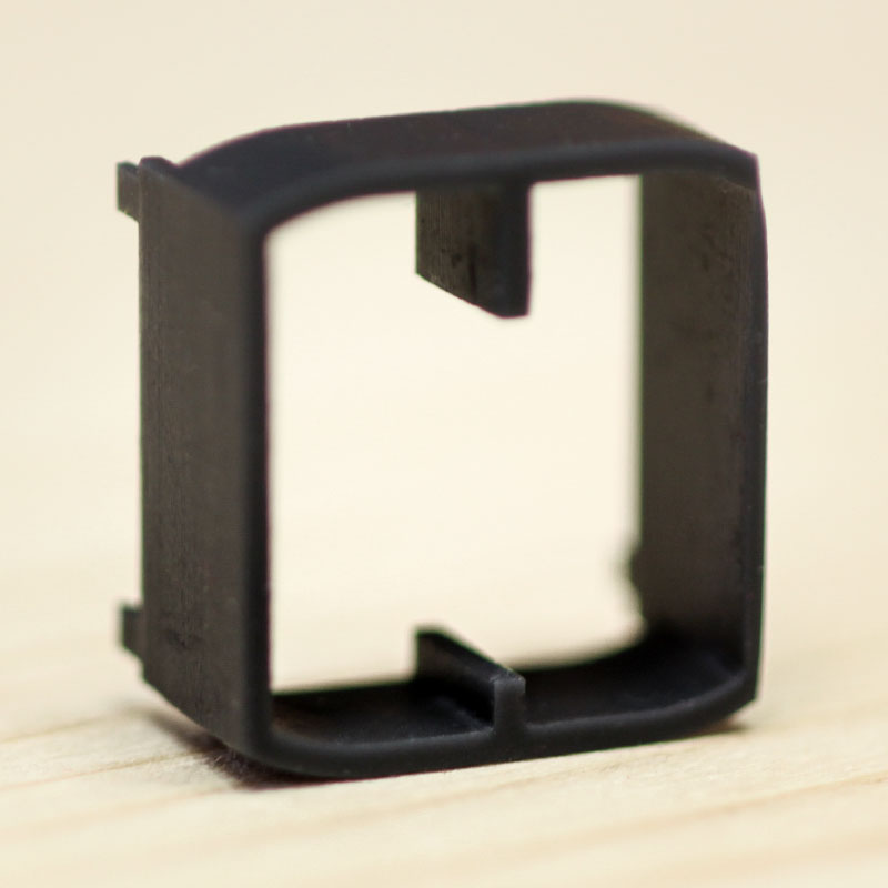
The short stretch of the middle wall aligns with the legs of the potentiometer. It has four thin guide legs that should easily fit into the four slots milled into the PCB.
The side walls are have a ledge so the part sits on top of the PCB.
Gently slot the part in place - it should not require any force to do so. Be careful not to break the guide legs. Once placed correctly, the part should have the same height as the Thonkiconn and potentiometers.
Place Through-Hole Capacitor#
Your kit contains one through-hole capacitor. It will sit under the Thonkiconn jacks, in a horizontal oriantation between PCB and panel.
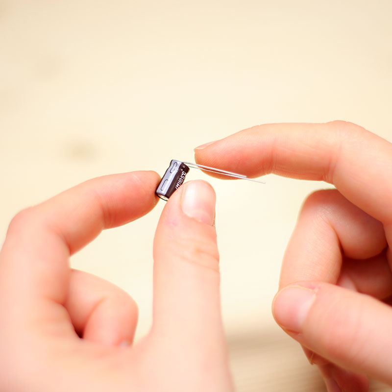
This means you need to bend its legs before you insert the capacitor. Note that the capacitor is polarized, so the orientaion in which you insert the component is vital.
The board is marked with + and -, the long leg on the capacitor is plus.
Test fit the capacitor so you know the orientation is correct, then bend the legs. Test fit the panel to make sure it sits tighly sandwiched between panel and PCB.
Place the through-hole capacitor but do not solder yet.
Warning
Double check that you have placed the capacitor in the correct orientation. Otherwise, the circuit will not work correctly, and you risk damaging other components when powering the board.
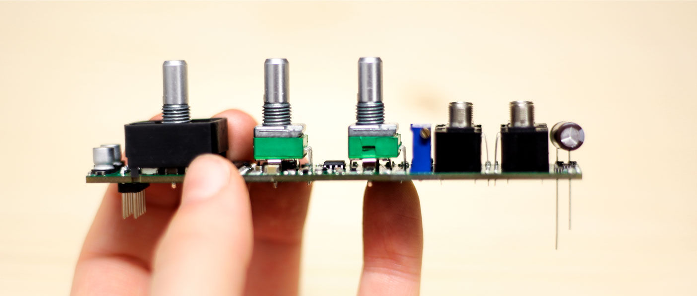
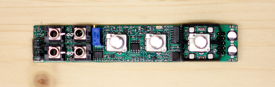
Place Panel + Thonkiconn Nuts#
Once all the components are in place, but not soldered, make sure everything lines up and put on the front panel. Screw on Thonkiconn nuts and the hex nuts for the Potentiometers, so the panel sits tightly atop the jacks and pots, and the jacks sit flush on the PCB.
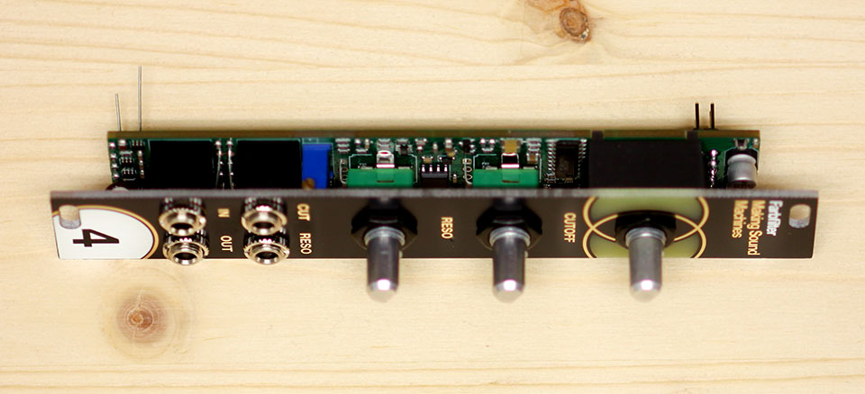
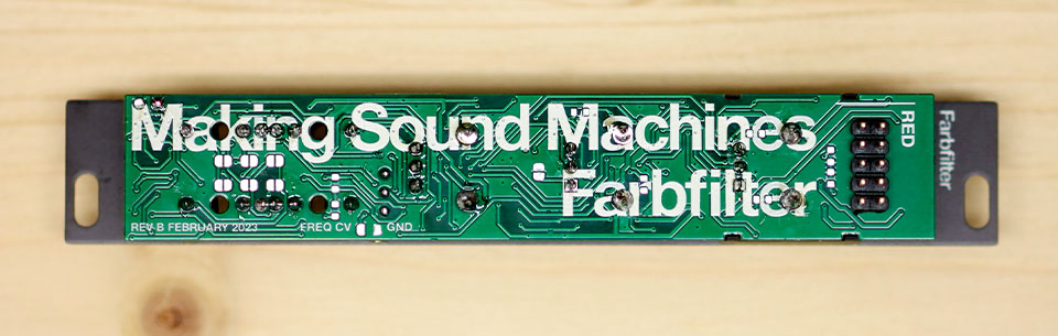
Wear it inside out#
When we were kids in school, we sometimes would go a whole day accidentally wearing our pullover or shirt inside out. We thought it would be a fun idea for our DIY modules too - so for Farbfilter, you can decide whether you want the module to wear its front panel inside out.
Farbfilter comes with one side that shows the module number at the bottom, in line with our other DIY modules. The other side does not have it. You decide!
Farbfilter wearing its front panel inside out
Solder Thonkiconn and Potentiometers#
Before you solder, make sure everything is as tightly sandwiched as possible. You can lay the module on its side before you tighten all the nuts, to make sure everything aligns and fits the panel.
Solder the jacks first, so the whole arrangement holds together.
Check one last time everything sits right, then solder the potentiometer points on the back.
Solder Through-Hole Capacitor#
Before you solder the through-hole capacitor, make sure it sits tightly sandwiched between Panel and PCB. It should also sit snuggly against the sides of the thonkiconn.
Check one last time everything sits right, then solder the through-hole capacitor points on the back.
Only once you’ve tested the functionality of your module, put on the Rogan soft touch caps.
Calibration#
The blue trim potentiometer sandwiched between front panel and circuit board, on the left hand side above the cutoff jack lets you adjust the combined voltage range of knob and CV.
The idea is to adjust this trim potentiometer to achieve the CV range you want to use the filter with. With the cutoff knob all the way down, patch a constant voltage to the CV in:
- 5V if you want to use a 0-5V range
- 8V if you want to use a 0-8V range
- 10V (max) if you want to use a 0-10V range
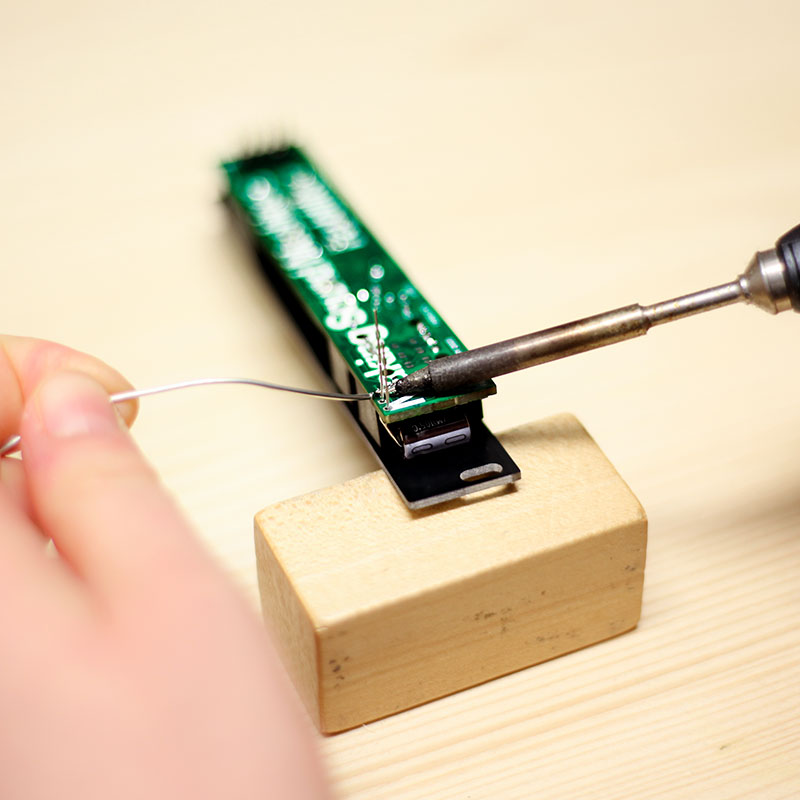
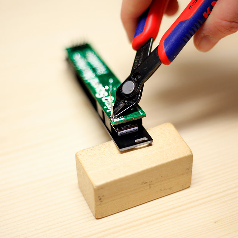
With a Multimeter, measure between the test points on the back of the module.
- The red probe goes to the pad labelled CV Range,
- the black probe goes to the pad labelled GND.
Adjust the trimpot until you get a 6V voltage reading. You have now calibrated the filter fully open the filter cutoff for the CV range you chose.