Tausend dB Kit – Build Guide
Some tools you will need#
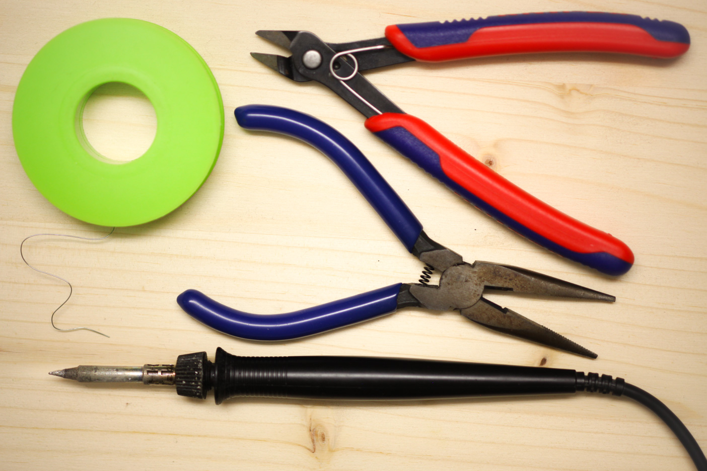
- A spool of solder. We use lead free 0.5mm
- Snipe-nose pliers
- Flat-nosed pliers
- And a soldering iron for electronics
Here’s what you will find in the kit#
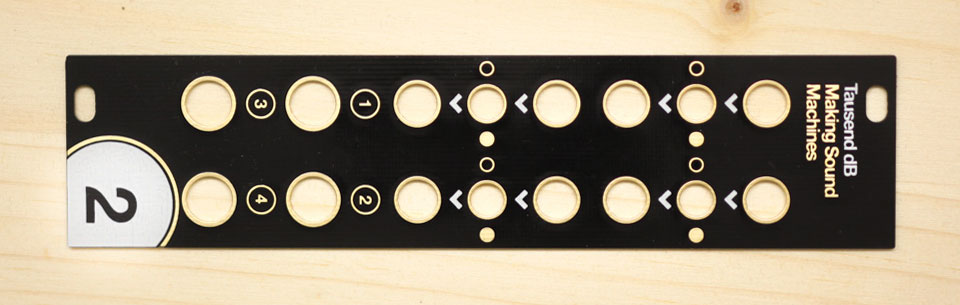
- The frontpanel
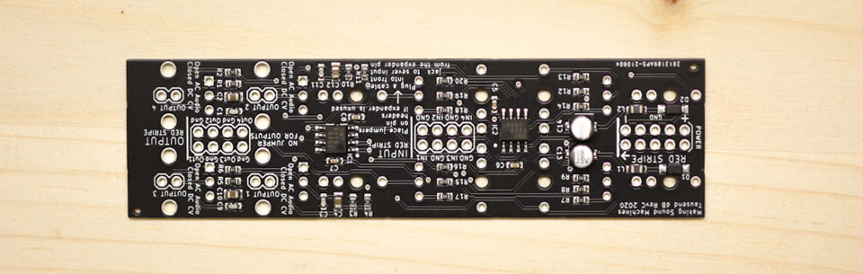
- The PCB with presoldered components
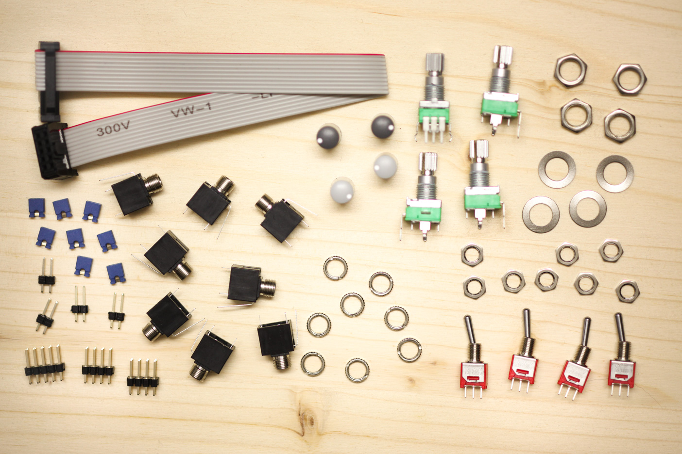
- 4x switches, with two hex nuts each
- 8x Thonkiconn jacks, and knurled nuts
- 4x potentiometers, with washers + nuts
- 4x potentiometer caps
- 8x jumpers
- 2x 4x2 pin headers
- 4x 2x1 pin headers
- 1x 2x5 pin header for power.
Build Guide#
All of the SMD components on the PCB have already been assembled for you, so this is a very quick build. However, it does require very careful and precise soldering.
Avoid touching the SMD components with your hands and be very careful not to touch them with your soldering iron. Take your time, and use an iron with a reasonably small tip.
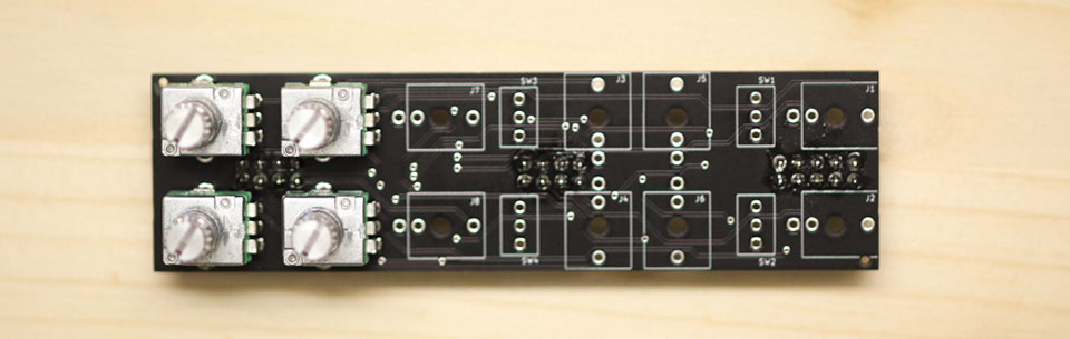
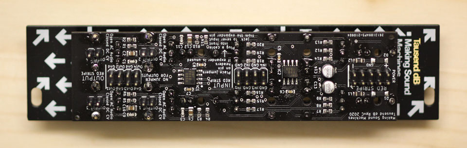
Back side - SMT component side
Turn the PCB over so you can see the surface-mount components - this will be the back side of the module.
2x5 Power Header#
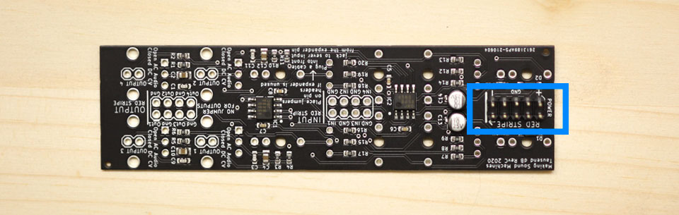
Start by placing the 2x5 power header where it says Power. Make sure that it sits on the correct side: the long pins should be on the same side as all the SMD components. The short pins stick through the PCB and should be soldered on the other side.
Solder two corner pins first, check that the pin header sits flush and reheat to adjust if necessary. Then solder the rest of the pins.
2x4 Expander Pin Header#
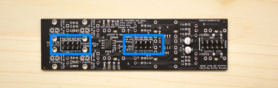
Now repeat the same process for the two 2x4 Expander pin headers. Insert them into the slots labelled Input and Output. Again, the long pins should be on the same side as all the SMD components. The short pins stick through the PCB and are soldered on the other side.
1x2 Pin Header#
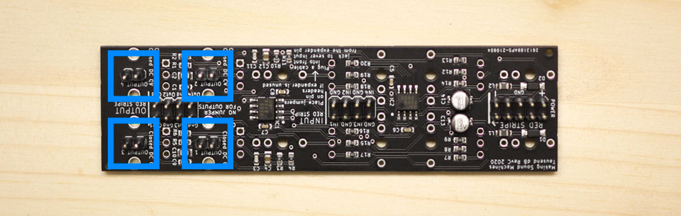
Finish the back side of the PCB by soldering the four 1x2 pin headers. The orientation is the same, with the long pins on the same side as the SMD components.
Place one header, flip over the board and balance it on the Power and Expander headers you already soldered. Solder one pin first, check that the pin header sits flush and perpendicular. Reheat to adjust if it sits slanted. Then solder the other pin.
Repeat until you have soldered all four 1x2 pin headers. Make sure they sit reasonably straight.
Flip over the PCB#
Next, flip over the PCB so you can see the side without any components yet. Place all the components onto the board, but do not solder anything yet.
Place Potentiometers#
Place the four 50k Audio potentiometers first, as they are the trickiest to place.
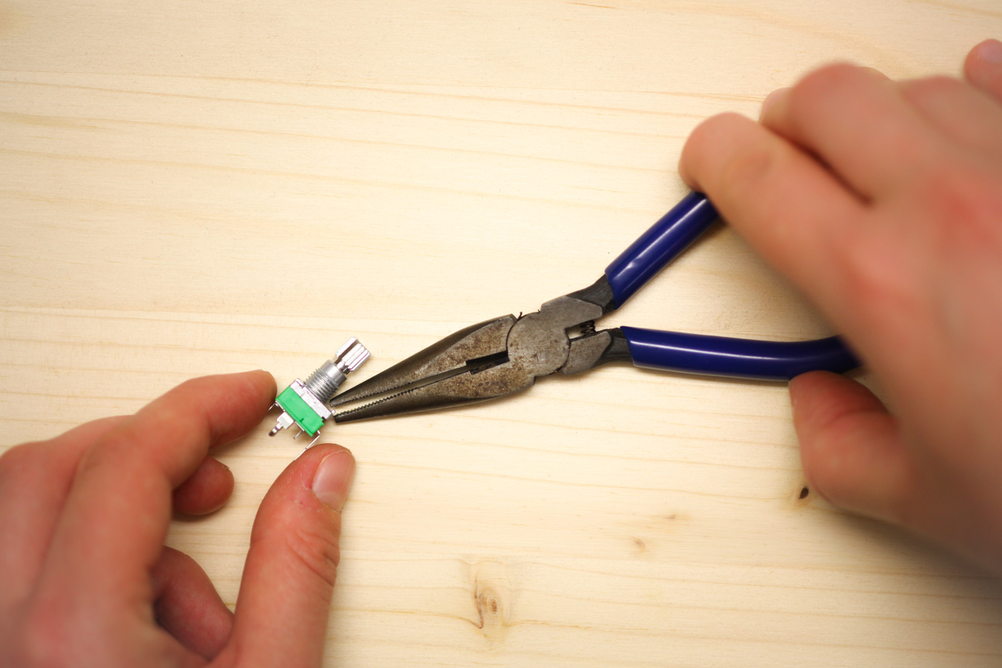
Use snipe nosed pliers to remove the little tab on the potentiometers’ top side. This is to ensure the pot sits flush with the panel.
You may need to squidge the legs in a little to make them fit. Be gentle as the pins may bend easily if you don’t line them up with the holes. Their footprints are marked with VR1 - VR4.
Warning
Double check that you have soldered all the pin headers (as described in the previous step). Once the pots and jacks are soldered in, the pin headers will become hard to reach with a soldering iron.
Place but do not solder yet.
Place Thonkiconn#
The groups of rectangular outlines marked with J and a number indicate where to place the 8 black Thonkiconn jacks. Place the jacks but do not solder yet.
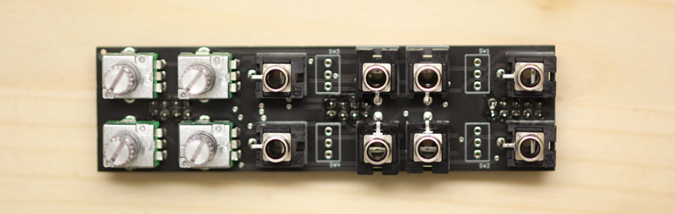
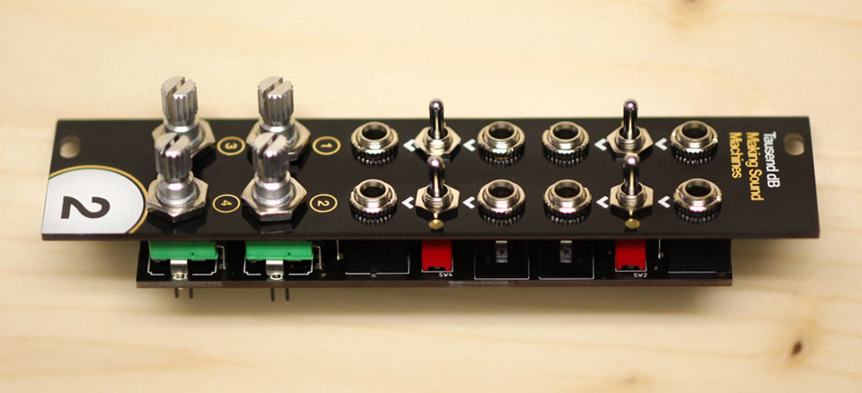
Place Switches#
The four subminiature switches go on the same side as the Thonkiconn, between the groups of sockets. Their footprints are marked with S and a number.
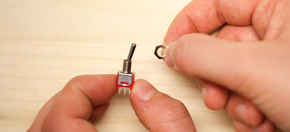
Screw one of the hex nuts onto each switch. This will help bring the switches to the same height as the jacks, so they will sit flush with the panel.
Place but do not solder yet.
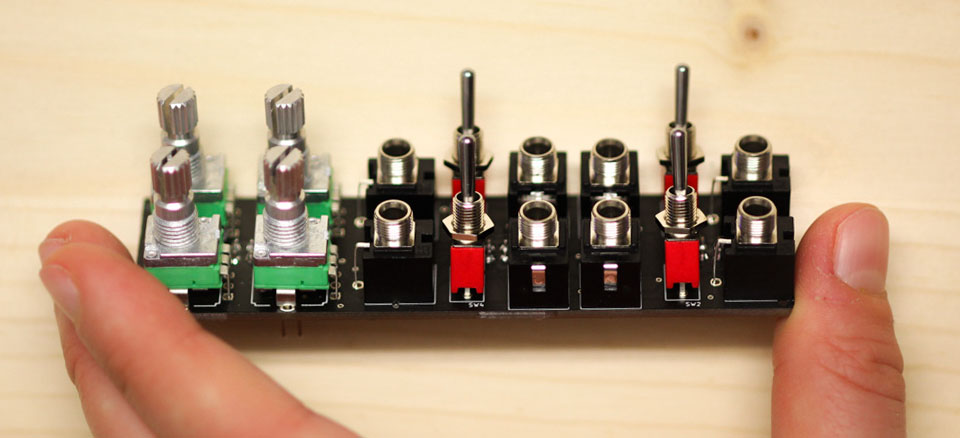
Place Panel + Thonkiconn Nuts#
Once all the components are in place, but not soldered, make sure everything lines up and put on the front panel. Screw on Thonkiconn nuts and the hex nuts for the Potentiometers, so the panel sits tightly atop the jacks and pots, and the jacks sit flush on the PCB.
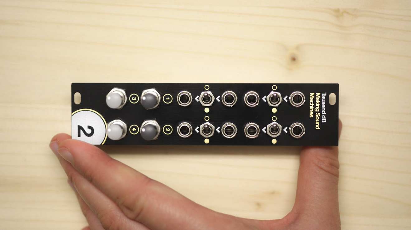
Wear it inside out#
When we were kids in school, we sometimes would go a whole day accidentally wearing our pullover or shirt inside out. We thought it would be a fun idea for our DIY modules too - so for Tausend dB, you can decide whether you want the module to wear its front panel inside out.
You will miss out on some of the panel markings like channel numbers, but be rewarded with a fun all-over arrow pattern. You decide!

Tausend dB wearing its front panel inside out
Once decided, screw on the second hex nut to hold each of the switches in place. The switches sit flush with the board, leaving enough of the pins to solder from the bottom side. Make sure everything is as tightly sandwiched as possible, so that it fits the panel.
Solder Thonkiconn, Potentiometers and Switch#
Solder the sockets first, so the whole arrangement holds together.
Check one last time everything sits right, then solder the rest of the points on the back - the potentiometers and the subminiature switches.
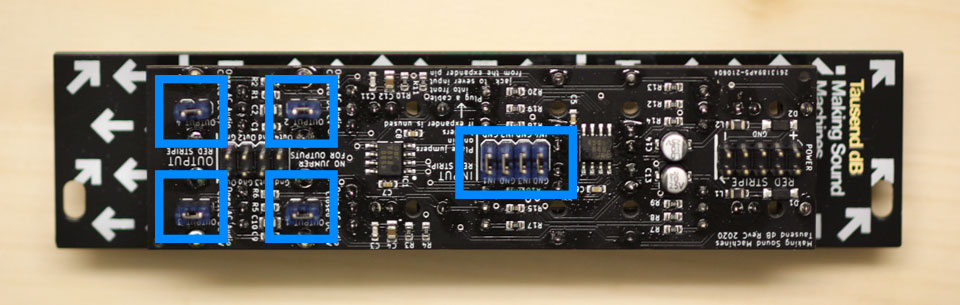
Place Jumpers#
Once everything is cooled down a little, place the jumpers on the pin headers in the back. Place four jumpers on the 2x4 pin header marked Input. Leave the 2x4 pin header marked Output unpopulated. Place four jumpers on the 1x2 pin headers.
Place Caps#
Once you’ve tested the functionality of your module, put on the T18 / T36 caps.
Congratulations, your build is done!#
Enjoy boosting and saturating with Tausend dB, use the performance mutes to cut out that racket (or add more!), and make sure you check out our suggested patches to make the most of your module.